Command Description
Command Description
Description of Command Functions
Blend
Blend refers to using the smooth blend at the corner instead of angular transition. Activating the blend can make the robot’s movement smoother, and the movement trajectory difference is shown in the following figure:
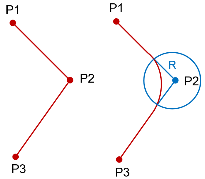
Trajectory without blend (left) and trajectory with blend (right)
Note:
- R stands for the radius (mm) of the blend.
- Activate blend at the point where you want to use blend. For example, in the figure above, you only need to activate blend at P2.
Speed and Acceleration
Joint Speed and Acceleration
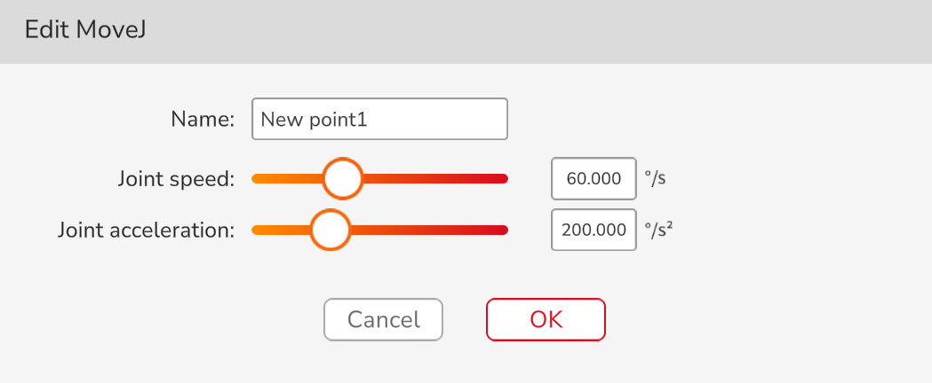
Joint speed and acceleration are the speed and acceleration of 6 joints, which specified in °/s, °/s ² respectively and can be used in MoveJ.
Linear Speed and Acceleration
Linear speed and acceleration are the speed and acceleration of the TCP, which specified in mm/s, mm/s² respectively and can be used in MoveL and MoveC.
Orientation Speed and Acceleration
Orientation speed and acceleration are the speed and acceleration of the whole robot when it rotates around X, Y or Z axis, which specified in °/s, °/s ² respectively and can be used in MoveL and MoveC.
Create Program

Meaning: The program that the robot is about to run.
Application: The commands to be executed are placed in order below the new program; click the commands to modify the program name.
Example: Let the robot perform joint movement from the starting point to the vertical posture.
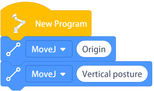
Note: If the module is not placed under “New Program”, it will not be executed.
Move Command
The movement position of the robot will change with the change of the coordinate system. When the user sets the position under a certain coordinate system, if the program is run after the coordinate system is switched, all points will automatically switch to the corresponding position. For example, the initial set point is (0°, 0°, 0°, 180°, 90°, 20°). After the coordinate system is switched, the point is switched to a position relative to the switched coordinate system (0°, 0°, 0°, 180°, 90°, 20°). Therefore, the user needs to set the coordinate system before editing movement commands or moving the robot (refers to the Software User Manual for details on how to switch the coordinate system).
MoveJ

Meaning: Make the robot perform joint movement.
Application: Click the command to open the setting interface and edit the name, speed, and acceleration of this command; select whether to use the Cartesian position; select stop or blend here; select stop conditions; edit the teach point.
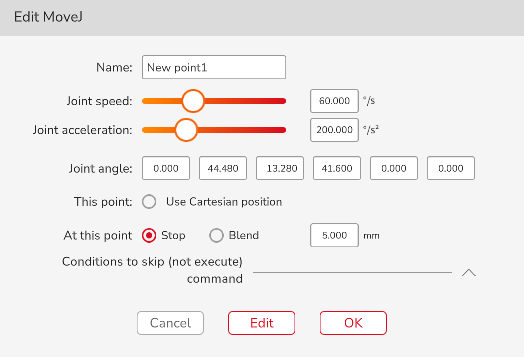
When using the MoveJ, if the Cartesian position option is selected, the robot will calculate the corresponding joint angle value based on the Cartesian position of the robot saved in the current movement, and then move to the setup position by MoveJ.
MoveJ with Cartesian Coordinate System

Meaning: Use the points recorded in the Cartesian coordinate system to perform joint movement.
Application: Use this command before the joint movement, and the subsequent joint movement will be performed in accordance with the points recorded in the Cartesian coordinate system. The movement mode is still joint movement, but the robot will automatically perform inverse kinematics.
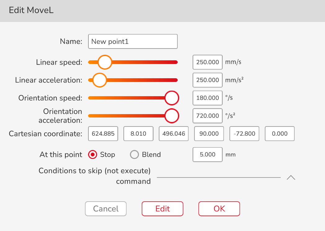
MoveL

Meaning: Make the end of the robot perform MoveL.
Application: Click the command to open the setting interface and edit the name, speed, and acceleration of this command; select stop or blend here; select stop conditions; edit the teach point.
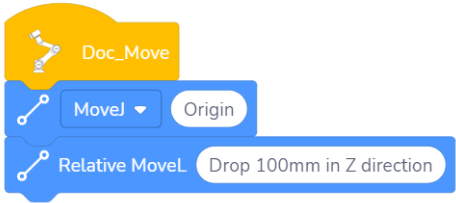
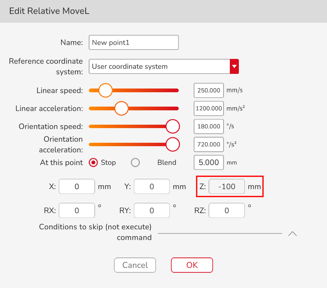
Relative MoveL

Meaning: A position change amount is set to let the robot perform the end MoveL relative to the current orientation, where the position change amount is an incremental value in the current user coordinate system.
Application: Click the command to open the setting interface, and edit the name, speed, acceleration, reference coordinate system, whether to use blend and stop conditions of this command as required; edit the amount of position change.
Example: The robot end moves 100mm along the negative direction of the Z axis of the current user coordinate system.
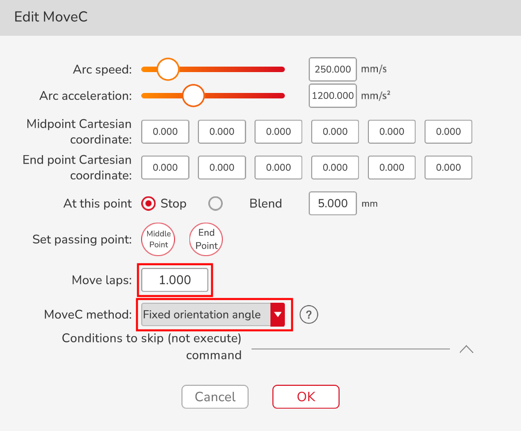
MoveC

Three points are required to complete the MoveC, including P0, P1, and P2. P0 is the last point of the previous command, P1 is the first point under the MoveC command, and the P2 is the second point under the MoveC command.
Move laps: The move laps can only be an integer. When the number of laps is 0, the MoveC trajectory is an arc from the initial point to the end point. When it is 1, the system will automatically calculate the whole circle through the setup initial point, passing point and end point. In this case, the MoveC trajectory is 1 full circle calculated by the system. When it is 2, the MoveC trajectory is 2 full circles calculated by the system, and the like.
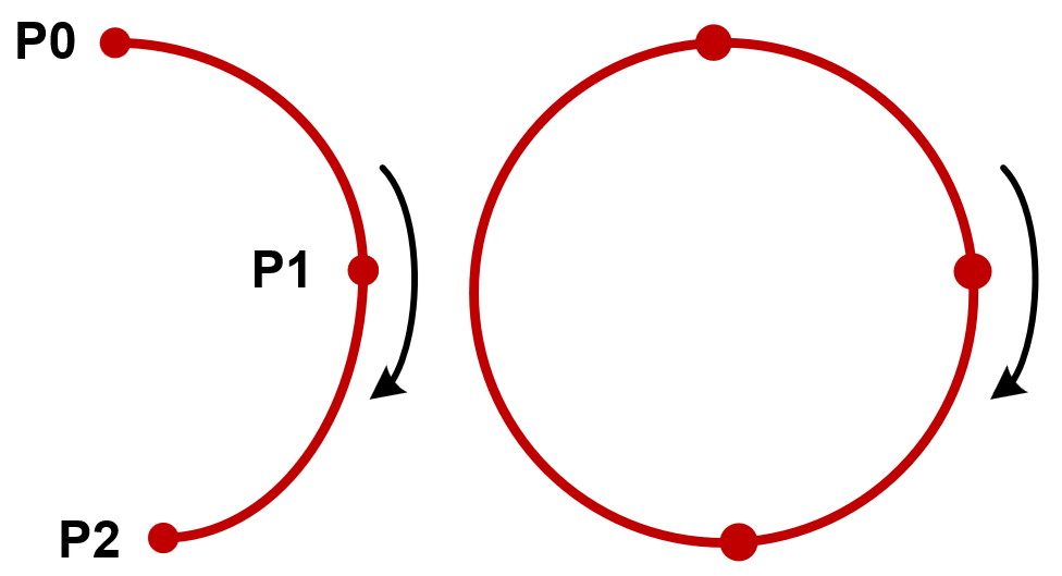
Move lap is 0 (left) and move lap is 1 (right)
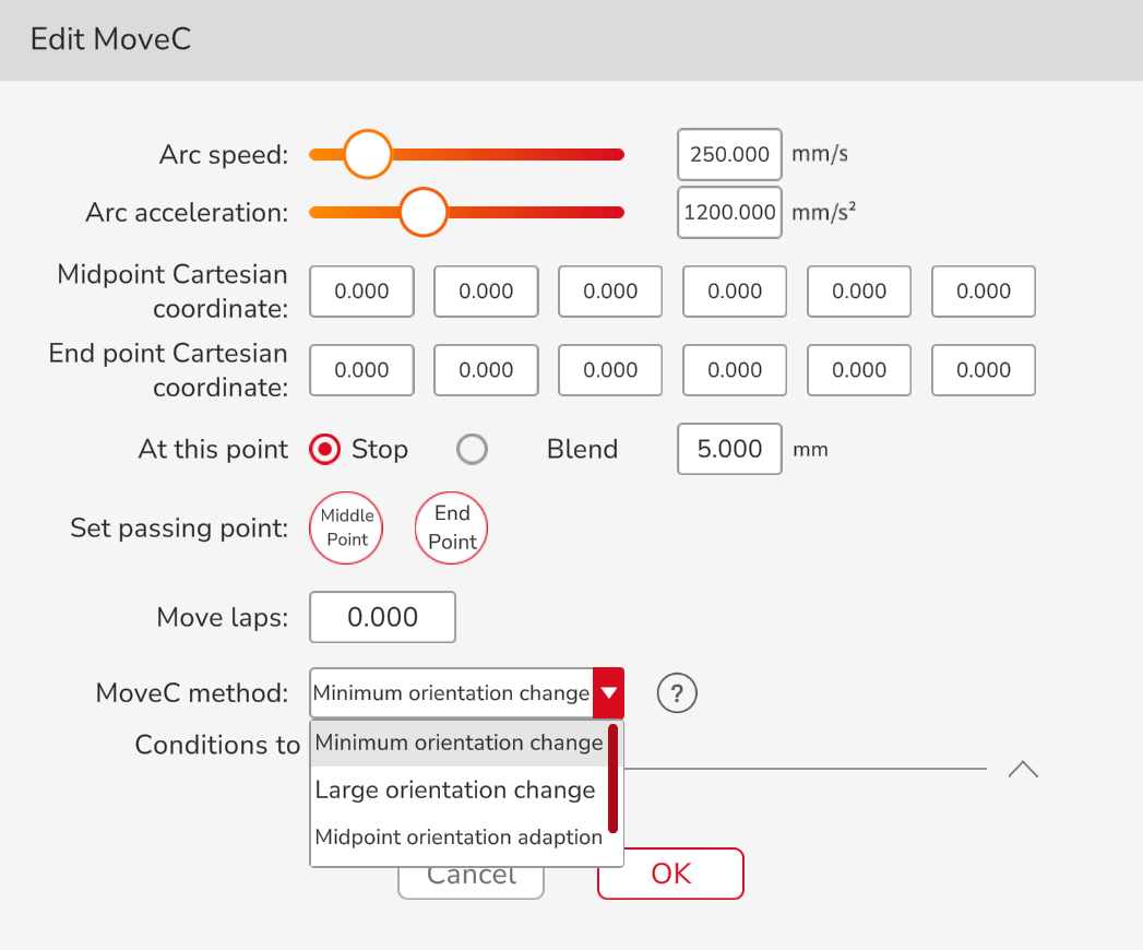
Move methods: There are 5 move methods, including minimum orientation change, large orientation change, midpoint orientation adaption, fixed orientation angle and lap rate mode. When the move lap is 0, you can use minimum orientation change, large orientation change, midpoint orientation adaption, and fixed orientation angle. When the move lap is not 0, can only use the lap rate mode.
Minimum orientation change: Robot moves by minimum orientation changes according to start point orientation, midpoint orientation, and end point orientation.
> A: Start Point B: End Point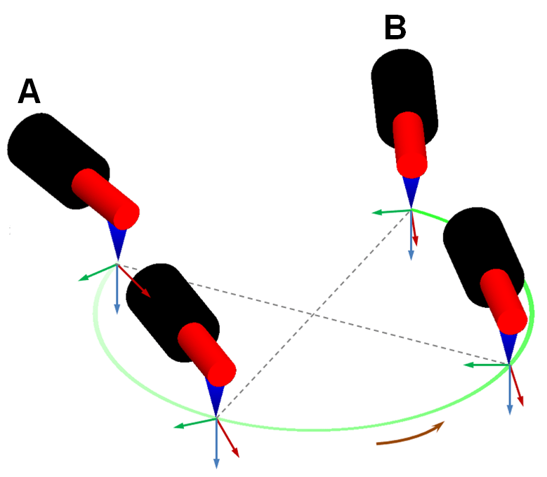
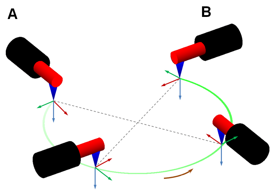
Large orientation change: Robot moves by large orientation changes according to start point orientation, midpoint orientation, and end point orientation.
> A: Start Point B: End Point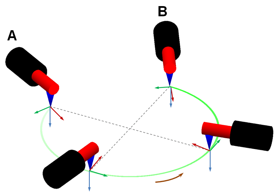
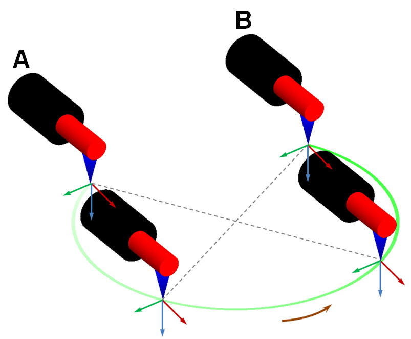
Midpoint orientation adaption: The MoveC trajectory is determined by start point orientation, midpoint position, and end point orientation; while the MoveC orientation of the robot is determined by midpoint orientation. Robot moves by the MoveC in the way of minimum or large attitude change.
or A: Start Point B: End Point
Lap rate mode: The robot TCP always points to the center of the circle to perform the MoveC according to the start point orientation, midpoint position, and end point position, regardless of the midpoint orientation, and end point orientation.
A: Start Point B: End Point
Fixed orientation angle:
When the start point orientation is different from end point orientation, the robot moves in accordance with the start point orientation and its TCP always points to the center of the circle according to the start point orientation, midpoint position, and end point position, regardless of the midpoint orientation, and end point orientation.
A: Start Point B: End Point
When the start point orientation is the same as the end point orientation, the robot moves in this fixed orientation and its TCP no longer points to the center of the circle.
A: Start Point B: End Point
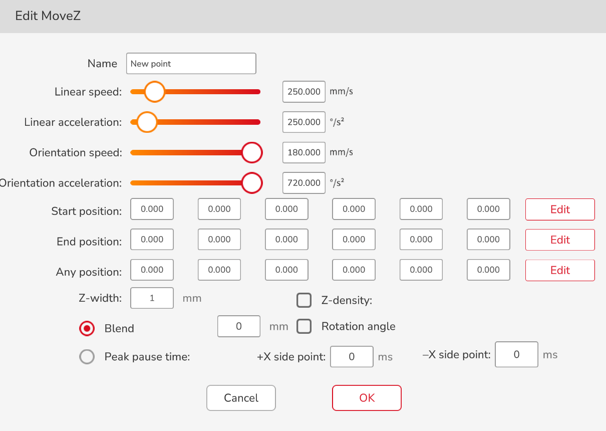
MoveZ

Meaning: The end of the robot maintains the current orientation and performs Z-shaped movement.
Application: Click the command to open the setting interface, edit the start position, end position and random passing position of the movement (the robot will perform Z-shaped movement on the plane determined by these three points), the width of the Z-shaped trajectory, the moving speed, the density of the Z-shaped trajectory, the blend or peak pause time (choose one).
Width: The width of the robot movement in the current plane.
Density: The distance between the peaks on the same side and the density determine the movement cycle of the robot; if the Z-shaped density is not set, the Z-shaped movement cycle is determined by the current movement speed of the robot.
Peak pause time: Every time a peak is reached (the red point in the trajectory diagram), the robot pauses, and the points on the +x side and-x side can be set with different pause time.
The plane perpendicular to the z axis of the user coordinate system is used as the plane of the robot movement by default, and the user can also customize the movement plane. For example, add a point to create a plane formed by the start point, the end point and the third point as the robot’s Z-shaped movement plane, where the third point direction is the +x direction.
The diagram of the MoveZ trajectory is as follows:
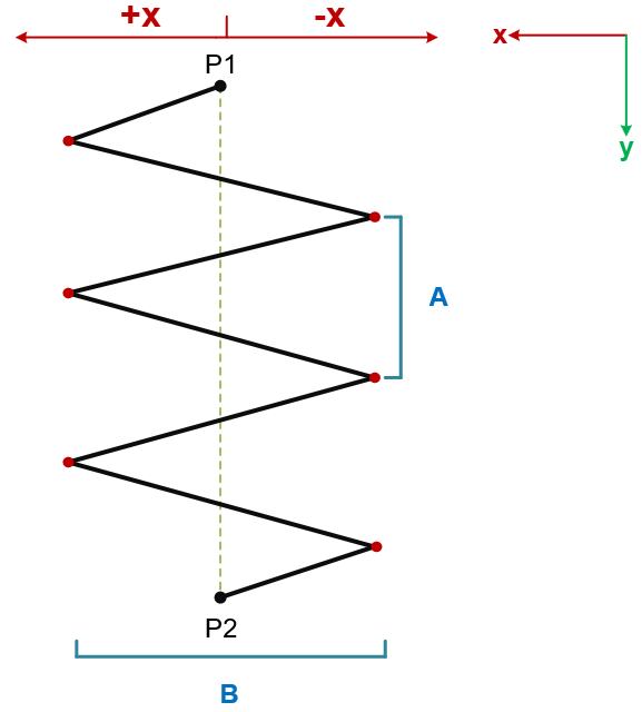
P1: Start point P2: End point
A: Density B: Width
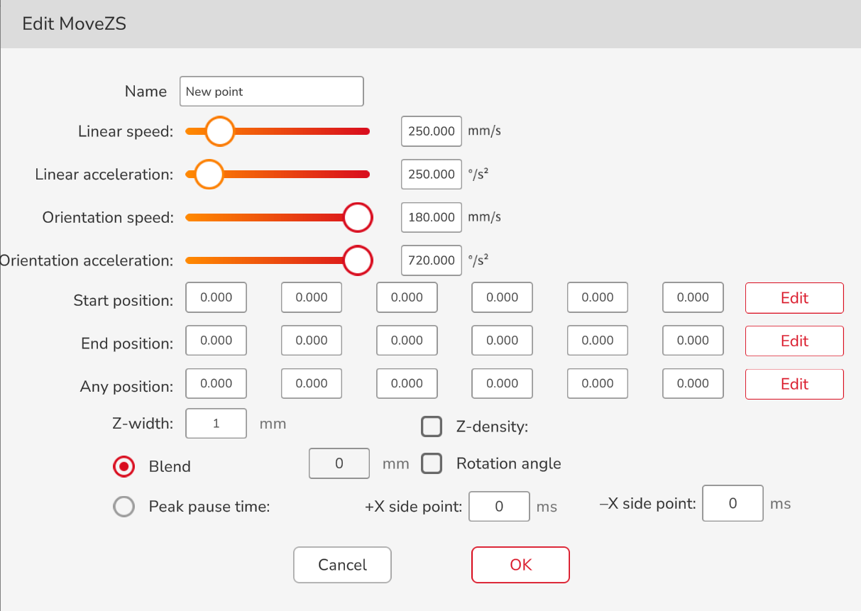
MoveZS

Meaning: The end of the robot rotates RZ while moving in the set direction.
Application: Click the command to open the setting interface, edit the start position, end position and random passing position of the movement (the robot will move on the user coordinate system determined by these three points), the width of the trajectory, the moving speed, the density of the trajectory, the rotation angle (45° by default), the blend or peak pause time (choose one).
Width: The width of the robot movement in the current plane.
Density: The distance between the peaks on the same side and the density determine the movement cycle of the robot; if the Z-shaped density is not set, the Z-shaped movement cycle is determined by the current movement speed of the robot.
Rotation angle: The rotation angle in the positive or negative direction of the x axis.
Peak pause time: Every time a peak is reached (the red point in the trajectory diagram), the robot pauses, and the points on the +x side and-x side can be set with different pause time.
The plane perpendicular to the z axis of the user coordinate system is used as the plane of the robot movement by default, and the user can also customize the movement plane, i.e. add a point to create a plane formed by the start point, the end point and the third point as the robot’s Z-shaped movement plane, where the third point direction is the +x direction.
The diagram of the MoveZS trajectory is as follows:
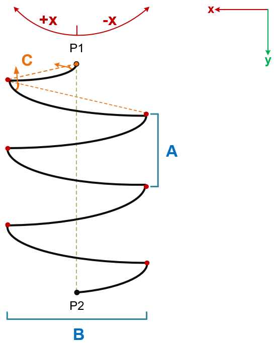
P1: Start point P2: End point
A: Density B: Width C: Rotation angle
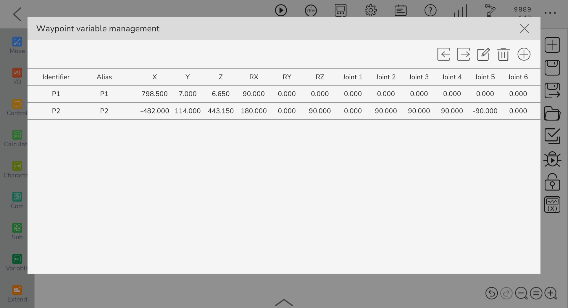
Waypoint Variable Management
The JAKA App supports the movement waypoint function. Users can define the movement waypoint in the waypoint variable management and use the corresponding movement waypoint command to control the robot to move to the setup waypoint position.
In the movement control interface, click the command bar on the left, enter the movement command interface, click “Settings”  button, and enter the waypoint variable management interface. The description of buttons on this page is as follows:
| Button | Name | Description |
|---|---|---|
 | Import waypoint | The name of imported file must be movepoints.zip. Click the button, select the file position, select waypoint file, and click OK. |
 | Export waypoint | Click the button, select the file position, and click OK. |
 | Edit waypoint | Click the button, select the waypoint variable to edit, click OK, and then App pops up waypoint variable editing page, edit the waypoint, and click OK. |
 | Delete waypoint | Click the button, select the waypoint variable to delete, click OK |
 | Add waypoint | Click the button, and App pops up waypoint variable editing page, edit the waypoint, and click OK. |
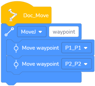
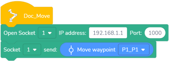
Move Waypoint

Meaning: The points of TCP during the movement.
Application: Click the command selection function to select custom waypoints or call waypoints defined in the waypoint variable management; click the command to open the setting interface and edit the alias of this command (in the custom mode, this cannot be modified), speed and acceleration; select whether to use shared parameters, the Cartesian position (MoveJ), and blend; select stop conditions (the program will skip this command when the robot meets the state set by the stop conditions).
When using shared parameters, the speed and acceleration of move waypoint command cannot be modified and decided by setup value in movement command box.
Note: This command needs to be used with the movement command box.
Example: The robot uses MoveJ to move from the position of waypoint 1 to the position of waypoint 2.
Move Command Box
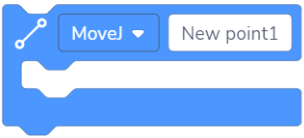
This works with the move waypoint command to let the robot perform MoveJ or MoveL. Click the command of movement switching function to switch MoveJ or MoveL, click the command to open the editing interface, and you can edit the name, speed, and acceleration of this command.
Pallet Waypoint

Meaning: Set the end point after the robot reaches each pallet point in the pallet program.
Application: Click the command to open the setting interface and edit the name, speed, and acceleration of this command; you may select stop or blend here; select stop conditions; edit the teach point (this command only takes effect in the pallet command).
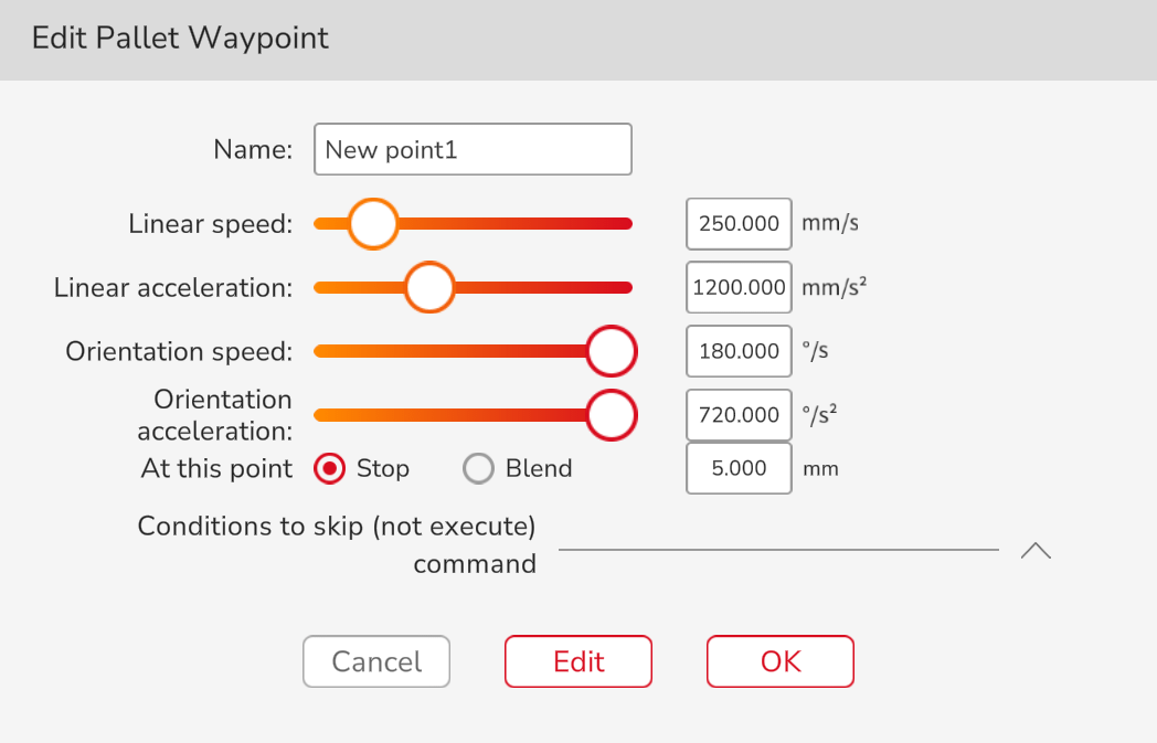
Note: This command only takes effect in the pallet box.
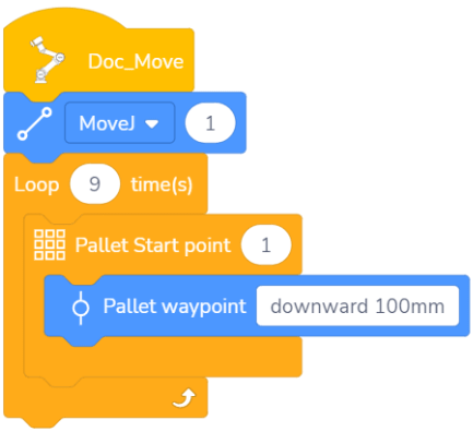
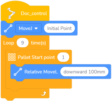
Example: The end of the robot walks in a 3x3 square pallet and moves down by 100mm at each point.
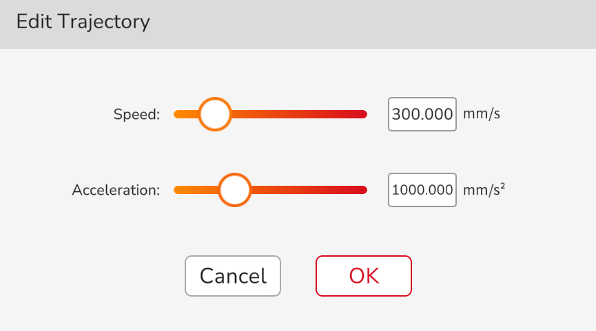
Trajectory Record

Meaning: The recorded trajectories are reproduced. Trajectories to be reproduced can be recorded by JOG or Freedrive.
Application: In the drop-down list of commands, you can select the trajectory to be used; click the command to open the setting interface, and you can edit the speed and acceleration of this command. The way to record the trajectory is shown in the Software User Manual.
Set Global Speed

Drop down the list to select an appropriate speed variable. After the global speed setting is enabled, the movement speed and acceleration of all subsequent MoveL and MoveJ commands will be consistent with the selected speed variable.
Close Global Speed

After this command is run, the global speed setup is disabled, and the subsequent MoveL and MoveJ restore the original movement speed and acceleration.
Get Move Waypoint Parameters

Meaning: Get the move waypoint information in the waypoint variable management.
Application: This can be sent to the host computer or assigned to variables.
Example: Read the information of move waypoint 1 in waypoint variable management. The host computer receives the move waypoint 1 information in waypoint variable management.
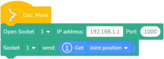
Get Robot Related Parameters

Meaning: Obtain the information of the robot's current joint position, tool center point position, flange center orientation, end payload, end force, collision sensitivity and system time.
Application: This can be sent to the host computer or assigned to variables. Refer to the Software User Manual for the data type of each parameter.
Example: The host computer receives the angle values of joint 1-6 of the robot.
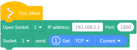
Obtain the Robot’s UCS or TCP

Meaning: Obtain the robot’s user coordinate systems or tool center points.
Application: This can be sent to the host computer or assigned to variables.
Example: The host computer receives the coordinate system value of the robot.
Is Position Reachable

Meaning: Determine whether a setup Cartesian position can be reached through Cartesian spatial movement based on the current position.
I/O Command
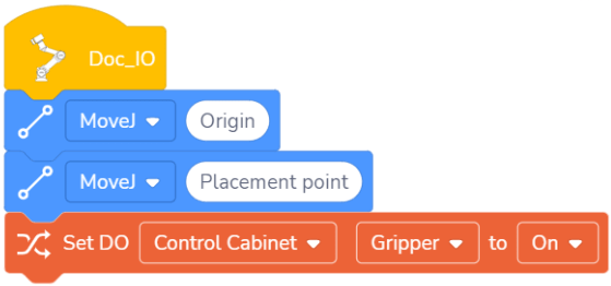
Set the Digital Output

This command is an immediate command. When it is used in the program, the DO signal set in this command will be output immediately.
Example: Move to the object placement point and release the gripper to place the object.
Set the Digital Output When Moving

This command is a non-immediate command. When it is used in the program, the DO signal will not be output immediately until the robot starts to move. The two commands adjacent to this command must both be move commands with blend enabled.
Await Digital Input

This command is used to await a DI signal. When the time input in the command is 0, the program will wait until the command is true before executing the program under the command. When the input waiting time is not 0, if the conditions in the command is true, the program under it will be executed im/media/entely. Otherwise, the program under it will be executed after waiting for the input time.
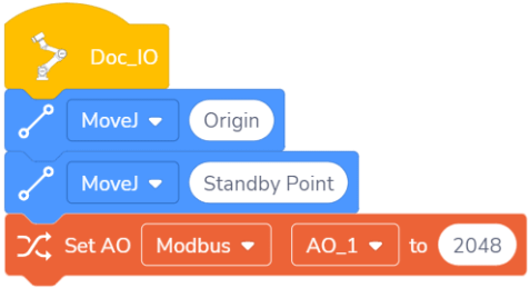
Set Analog Output

This command is an immediate command. When it is used in the program, the AO signal set by it will be output immediately. The value of the analog output signal can be filled in the oval white box, and the value range is –65535 ~ 65535.
Example: When the robot moves to the standby point, the value of the control cabinet AO1 is set to 2048.
Set Analog Output When Moving

This command is a non-immediate command. When it is used in the program, the AO signal will not be output immediately until the robot starts to move. The value of the analog output signal can be filled in the oval white box, and the value range is –65535 ~ 65535. The two commands adjacent to this command must both be move commands with blend enabled.
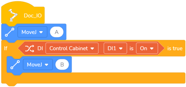
Digital Input

This command is used to obtain the status of the digital input and needs to be used with other commands. It can be used with if command. When the actual DI status is consistent with the setup status in this command, the result is “True”.
Example: Determine the status of the current digital input. If the current digital input DI1 is ON, the robot moves from point A to point B.
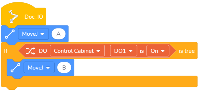
Digital Output

This command is used to obtain the status of the digital output and needs to be used with other commands. It can be used with if command. When the actual DO status is consistent with the setup status in this command, the result is “True”.
Example: Determine the status of the current digital output. If the current digital output DO1 is ON, the robot moves from point A to point B.
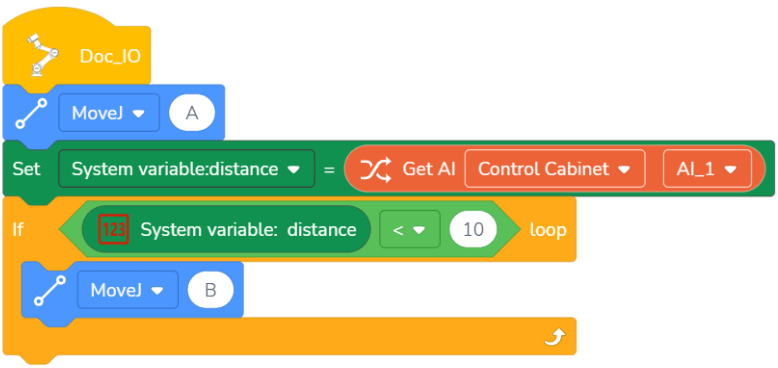
Get Analog Input

This command is used to obtain the status of the digital input and needs to be used with other commands. The value of the analog input can be assigned to the variable by putting this command into variable command.
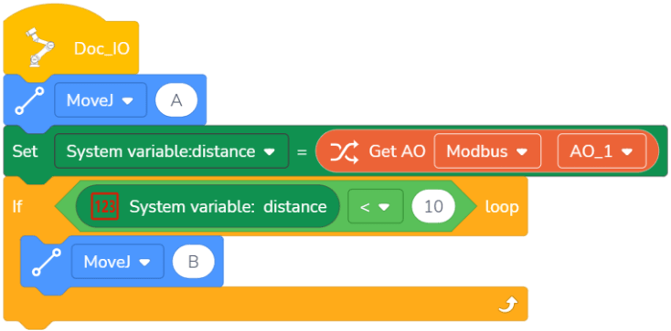
Example: Assign the current analog input to the system variable named distance. If the distance value of the system variable is less than 10, the robot moves from point A to point B.
Get Analog Output

This command is used to obtain the status of the analog output and needs to be used with other commands. The value of the analog output can be assigned to the variable by putting this command into variable command.
Example: Assign the current analog output to the system variable named distance. If the distance value of the system variable is less than 10, the robot moves from point A to point B.
Control Command
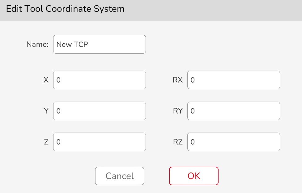
Set Tool Coordinates


When the coordinate system changes during the running of the program, it is necessary to use this command to make the commands after this command move under the coordinate system set by this command. This command only has an effect on the MoveL, and has no effect on the MoveJ. There are two ways to set the tool coordinate system in the control command:
Manually input TCP.
Select the TCP established in the settings (see the Software User Manual for how to establish TCP).
Click the command to open the setting interface, and you can edit the name and values of the coordinate system. This coordinate system is available only in this program (the default TCP is the end flange center).
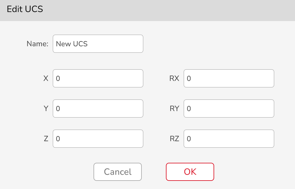
Set User Coordinates


When the coordinate system changes during the running of the program, it is necessary to use this command to make the commands after this command move under the coordinate system set by this command. This command only has an effect on the MoveL, and has no effect on the MoveJ. There are two ways to set the user coordinate system in the control command:
Manually input the user coordinate system.
Select the user coordinate system established in the settings (see the Software User Manual for how to establish the user coordinate system).
Click the command to open the setting interface, and you can edit the name and values of the coordinate system. This coordinate system is available only in this program (the default user coordinate system is the world coordinate system).
Set Payload and Mass of Center

When the payload changes during operation, it is necessary to use the command to set the payload. During operation, if the setup payload does not match the actual payload, the robot may tremble or the App pops up collision by mistake.
This command is used to modify the payload and the mass of center during the operation of the program. There are two ways:
Enter the actual payload and mass of center directly in the table.
Insert the number variable in the white oval box, and the initial value of the variable is the payload or mass of center value you want to set.

Waiting Command


There are two types of waiting commands:
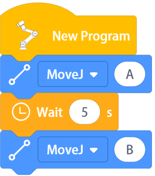
Specific waiting time: When running the program, the program will pause and continue to run after waiting for the input time. If the set waiting time is 0s, the robot will wait forever.
Example: After the robot moves to point A, it pauses for 5s and continues to run.
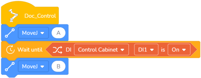
Specific waiting condition: After the condition is inserted in the box, when running to this command, the robot will keep waiting until the condition is met before continuing to run the program;
Example: When the digital input DI1 is ON, the robot moves from point A to point B.
Loop Command
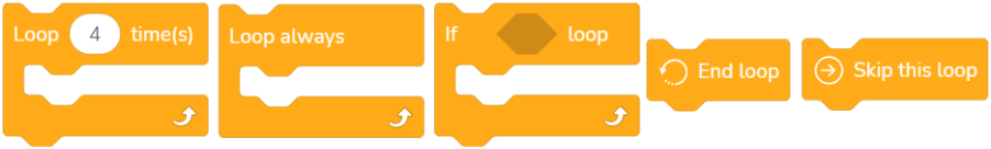
There are five types of loop commands:
Loop for specific times: When the program runs this command, the commands included in the loop command will not end until it is repeatedly run for the time you enter in the loop command or until it runs to the end loop command.
There are two ways to use this command:
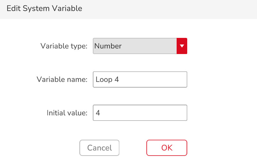
Enter loop time in the white oval box.
Insert the number variable in the white oval box, and the initial value of the variable is the loop time.

Loop always: When the program runs this command, it will always loop the commands in this command until it runs to the end loop command.
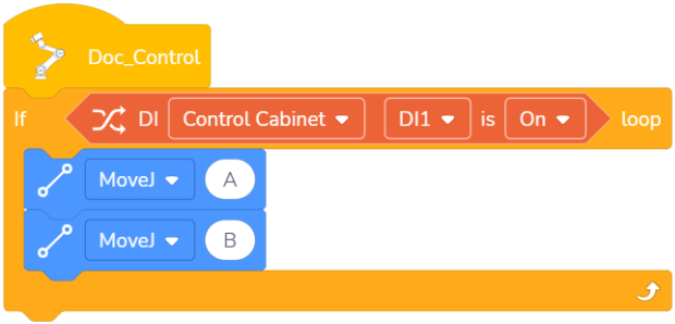
If…loop: You can insert command in the diamond space of the “If…Loop” command as a condition. When the condition in the diamond space is met, the commands in this “If…Loop” command box will be looped until the condition is not met or it runs to the end loop command.
Example: If the condition is true, the robot will repeat the movement between points A and B.
End loop: This command should be used with loop commands and if commands. When conditions are met, the loop closest to the end loop command is terminated. A condition is added before this command, and the current loop is terminated immediately if the condition is true.
Example: If the end loop condition is false, the robot moves from point A to point D. If the end loop condition is true, the robot only moves from point A to point B, and then skips the loop without executing the MoveJ of CD, and the program ends.

Skip this loop: This command needs to be used with loop commands and if commands. When conditions are met, the loop closest to the end loop command is terminated. A condition is added before this command. The current loop is skipped if the condition is true, and then the program returns to the original position of the loop to continue the loop.
Example: If the condition for skipping this loop is false, the robot moves from point A to point D. if it is true, If the skip loop condition is true, the robot only moves from point A to point B, skip the MoveJ of CD commands, and continue to execute the loop from the beginning without jumping out of the current loop.

If Command
There are two types of if commands:
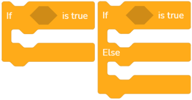
- If:
This command is used to check whether the condition in the command box is true, and if the condition is true, the program inside the command box is run, otherwise it is not run.
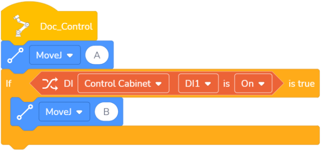
Example: If the current digital input DI1 is ON, the robot moves from point A to point B; If the current digital input DI1 is OFF, the robot only performs MoveJ of point A.
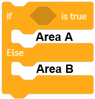
- If else:
This command is used to check whether the condition in the command box is true. If the condition is true, the program in Area A is run. If the condition is false, the program in Area B is tun, as shown in the following figure:
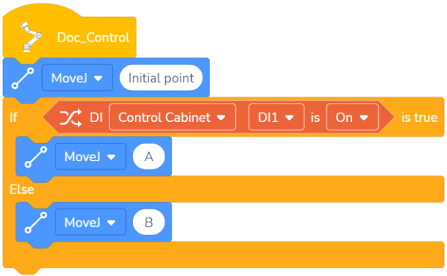
Example: If the current digital input DI1 is ON, the robot moves to point A, otherwise the robot moves to point B.
Pallet Command

The pallet command is mainly used for palletizing, that is, items are stacked on the pallet according to the rules. This command needs to be used with the loop command.
There are three types of pallets: one-dimensional (line segment), two-dimensional (quadrilateral), and three-dimensional (cube). The trajectories are as follows:
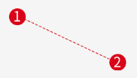
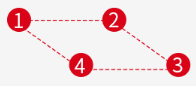
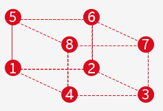
One-dimensional Two-dimensional Three-dimensional
The operation steps are as follows:
Select the pallet type.
Set the speed, acceleration, and whether to use blend, and select stop conditions.
Edit the point: one-dimensional pallets need to set 2 points, two-dimensional pallets need to set 4 points, and three-dimensional pallets need to set 8 points. Click the pallet command to open the pallet editing interface, and click the number to enter the editing interface to editing points. Before editing a point, switch to the desired coordinate system and ensure that all points are in the same coordinate system.


One-dimensional Two-dimensional Three-dimensional
Set the total count from Point X to Point X: The total count is the number of artifacts, which is also the total number of points including starting point and ending point. For example, in a one-dimensional pallet, if the total count from point 1 to point 2 is set to 3, the system will automatically divide the line segment from point 1 to point 2 into two equal segments and set a point at the midpoint. If the total number is 4, the system will automatically divide the line segment from point 1 to point 2 into three equal segments and set two points at the dividing points, as shown in the following figure.

Total count is 3 Total count is 4
Set the start point: There are three ways to set the start point:
- Enter the start point number or variables in the white oval box (when the value is less than 1, the App will pop up an error; when the value is greater than the total number of points, it will start from the first point of the pallet; when the value is within the range from 1 to the total number of points, the robot will start to run from the entered number). For example, for a two-dimensional pallet, if the total count from point 1 to point 2 is 3, and the total count from point 2 to point 3 is 3, then the total number of points is 3×3=9.
- Add MoveJ or MoveL before the pallet movement. The start position of the movement is the initial point, and the end position is point 1.
Edit the loop command: The loop time is related to the number of points. For example, to set a 3×3 pallet, if you want to pass through the 9 points, the time should be set to 9.
Insert other commands: Other commands can be inserted into the pallet command box to enable the robot to complete the desired action.
Example: The end of the robot walks in a 3x3 square pallet and moves down by 100mm at each point.
Conveyor Tracking Command

This command makes the robot end follow the movement of the conveyor in real time. Before using the App to carry out the conveyor tracking operation, the environment needs to be set up first, that is, connect the encoder to the control cabinet, and connect the robot by Modbus poll. There are two types of conveyor tracking:
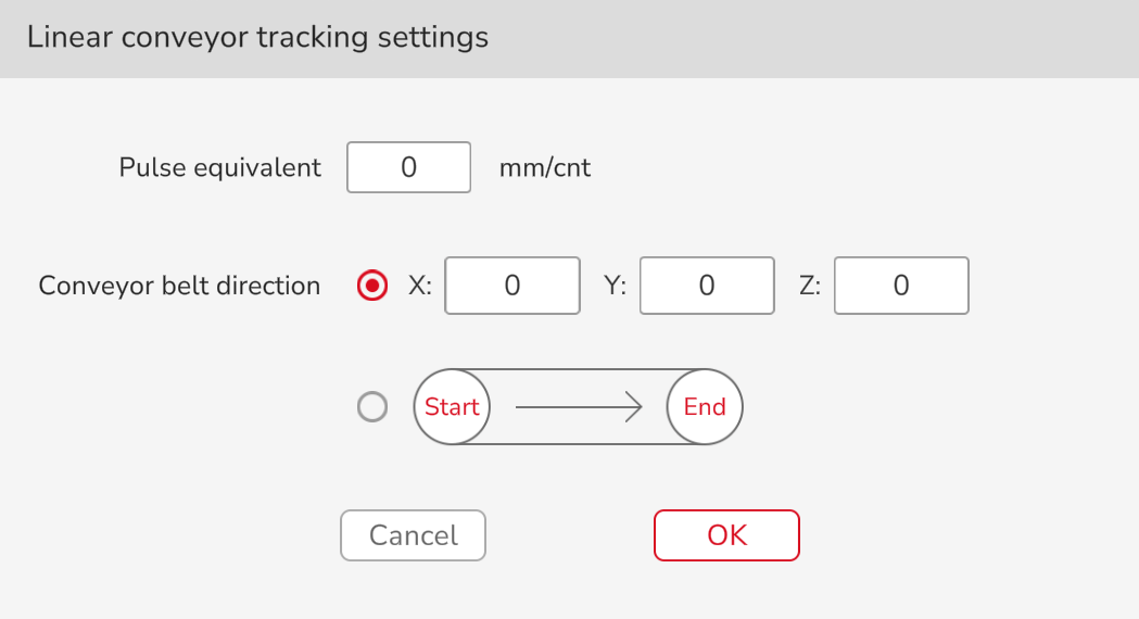
Linear conveyor tracking:
Calculate the pulse equivalent: Calculate the pulse equivalent by reading the change in the encoder pulse value and measuring how far the conveyor has moved. (The distance can be measured by a caliper, and the pulse value can be read by Modbus). The pulse equivalent calculation formula is as follows:
Pulse equivalent = Distance (mm)/Pulse value (cnt)
Set the conveyor direction: There are two ways to set the direction of the conveyor:
Manual input: The conveyor direction XYZ indicates the direction of the position [0,0,0] pointing to [X, Y, Z] under the user coordinate system. For example, setting [1,0,0] indicates the positive direction along the X axis of the user coordinate system.
Set the start point and end point: Click the start point (end point) to confirm the robot’s position. The current command will automatically calculate the movement direction of the conveyor according to the two points. The direction of the conveyor will point from the start point to the end point.
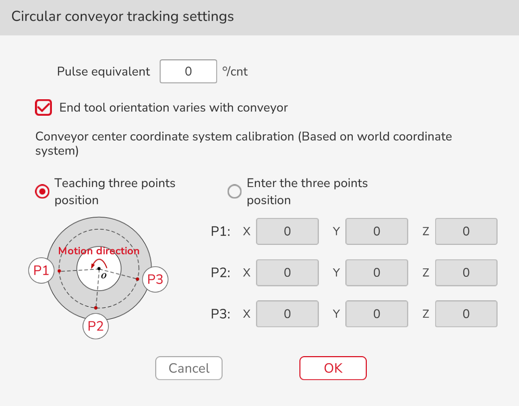
Circle conveyor tracking:
Calculate the pulse equivalent: The pulse equivalent is the angle at which the conveyor rotates when the encoder sends a pulse. It can be determined by the angle at which the conveyor rotates when the encoder finishes a lap (the pulse value can be read by Modbus). The pulse equivalent calculation formula is as follows:Pulse equivalent = Angle (°)/Pulse value (cnt)
Ensure that the orientation of the end tool varies with conveyor:
- When the option “End Tool Orientation Varies with Conveyor” is selected, during the movement of the circle tracking conveyor, the end tool also synchronously rotates around the rotation axis of the conveyor, that is, the orientation of the end tool in the current user coordinate system is changing;
When the option “End Tool Orientation Varies with Conveyor” is not selected, the orientation of the end tool in the current user coordinate system remains unchanged during the movement of the circle tracking conveyor;
Calibrate the center coordinate system of the conveyor: The center coordinate system of the conveyor is determined by the position of the three points on the conveyor: P1, P2, P3. The calibration of the positions of P1, P2 and P3 can through teaching their positions or directly inputting their coordinates.
Note: P1, P2, and P3 must be selected in turn according to the direction of conveyor movement, and their positions must be relative to the world coordinate system.
When “Teaching Three Points Position” is selected, follow the steps below to carry out circle conveyor tracking:
Determine a point P on the conveyor, and rotate the conveyor belt to move the point P to the working range of the robot;
Click the command to enter the setting interface of circle conveyor tracking, click
 to enter the movement control interface, control the robot movement in the interface to make the end of the robot coincide with point P (the user coordinate system at this time must be the “world”), and click “OK” to complete the calibration of P1;
Lift the robot tool and rotate the conveyor belt at a certain angle in the movement direction of the conveyor;
Click
 in the setting interface of circle conveyor tracking to enter the movement control interface, control the robot movement in the interface to make the end of the robot coincide with point P again (the user coordinate system at this time must be the “world”), and click “OK” to complete the calibration of P2;
Lift the robot tool again and rotate the conveyor belt at a certain angle in the movement direction of the conveyor;
Click
 in the setting interface of circle conveyor tracking to enter the movement control interface, control the robot movement in the interface to make the end of the robot coincide with point P again (the user coordinate system at this time must be the “world”), and click “OK” to complete the calibration of P3;
Click “OK” in the setting interface of circle conveyor tracking to complete the calibration of the center coordinate system of the conveyor.
Write program: Insert the move command into the conveyor tracking command box (the move command in the conveyor tracking command box must not be the MoveJ).
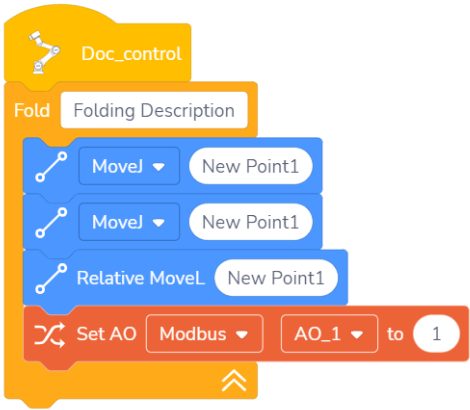
Command Fold

Drag the command in this command box to fold it into a single command.
Example: Fold the following commands.

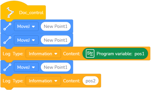
Output Log Type and Log Content

This command enables the user to customize the content of output logs. In the command drop-down list, can select the log type, including message, warning, and error. Enter a value in the log content or drag a string variable. The output log content can be viewed in the App log information.
Example: Output the log contents pos1 and pos2 when the target position is reached.
Stop/Pause Program

In the command drop-down list, you can select to pause or stop a program, and this command can be added at any position in the program to stop or pause the program at this position.
Multi-threaded Command
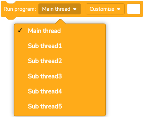
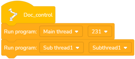
- Run programThis command is set to call other programs in an already ongoing main program. Whatever is being called can be set as a main thread or sub-thread. When it is set as a main thread, upon reaching this command, the main program will run and finish the commands within this main thread first, then return to run other subsequent commands in. This is "operate in sequence". When it is set as a sub-thread, upon reaching this command, the main program will create a parallel thread to run and finish the commands within this sub-thread, while the other commands in the main program can be executed at the same time. This is "operate in parallel". Up to 5 sub-threads can be added to run in parallel with the main thread. Sub-threads will also end when the main thread ends. When “Customize” is selected, fill in the white box with the location of the calling program file. Example: The first command executes the program file named 231 in the main thread mode, and the second command executes the program file named Subthread1 in the sub-thread mode. The example program is as follows:
Thread operation

 There are two types of thread operation: wait and destroy.
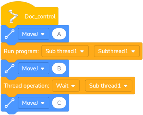
Wait: When the command is run, wait for the programs in it to finish before running the programs after this command.
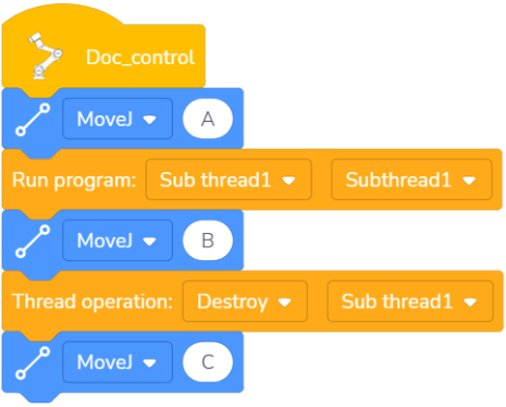
Destroy: When the command is run, the programs in it are terminated, and the programs after this command continues to run.
Example 1: After the robot moves to A, it executes Sub-thread 1 and moves to B at the same time. After Sub-thread 1 finished, the robot moves to C.
Example 2: After the robot moves to A, it executes Sub-thread 1 and moves to B at the same time. Stop the Sub-thread 1, and the robot moves to C.
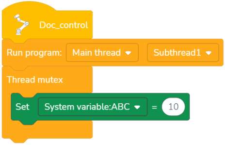
Thread mutex

When there are multiple subprograms in a main program, and the different programs have the same command, the use of thread mutex command can prevent conflicts between different commands. The same command can be placed in the thread mutex command box to prevent program errors due to the same command being executed at the same time. The execution order of the same command: if a command is executed first, then other identical commands are stopped until the execution of this command is completed.
Note: The thread mutex command is only valid for variables.
Example: Sub-thread 1 is inserted into the main thread, and sub-thread 1 also contains the set system variable ABC. To avoid conflicts, the set system variable ABC can be placed in the command box of thread mutex.
Calculate Command
Calculation Symbol

Six calculation methods are available, including addition (+), subtraction (-), multiplication (*), division (/), rem (%), and exponentiation (**).
Mathematical Function Calculation

Provide mathematical functions to calculate sine, cosine, tangent, arcsin, arccos, arctan, natural exponent, natural logarithm, round-up, round-down, rounding, absolute value, and square root.
Comparison Operator

Comparison operators are available, including less than, equal to, greater than, not equal to, less than or equal to, greater than or equal to, and returns true when the condition is met.
AND

If both conditions in the diamond box are true, the returned result is true.
OR

If two conditions in the diamond box are true or one of them is true, the returned result is true.
XOR

If only one of the two conditions in the diamond box is true, the returned result is true.
NOT

If the conditions in the diamond box are not true, the returned result is true.
Position Calculation
Addition

Add the two positions.
Subtraction

Subtract the two positions.
Inverse transform

Matrix inversion. The calculation position is in the Cartesian coordinate.
For example, if the coordinate of the point P is [10,10,10,10,10,10], the inverse transform position is [-10,-10,-10,10,-10,-10].
Position transform

Drag in the position variable or teach point, which are the incremental change of the robot's start orientation and relative start orientation, and the returned value of the command is the change result.
Note: The position is calculated in Cartesian coordinates.
Position distance calculation

Drag in the position variable or teach point, and the returned value of the command is the distance between the two points.
Interpolation Point

The command calculates the interpolation point between two points according to the given coefficient, and the range of the coefficient is 0-1. Drag in the position variable or teach point, and the returned value is the position of the interpolation point.
For example, set the coefficient as 0.5 or 0.25, and the position of the interpolation points are red points in the figure below:

0.5 0.25
Plane Transform

The command is used to make a point change in the XY (YZ/ZX) plane. The base point rotates around the Z (X/Y) axis, then translate along the X (Y/Z) axis, and translate along the Y (Z/X) axis. Position variable, array variable, or teach point can be dragged to the base point, and the returned value of the command is the changed position.
Example: First, translate P along the direction of the user coordinate system [0,10,10], and then rotate P by 10° around the X axis of the user coordinate system.

Inverse (Forward) Kinematic

Inverse kinematic of the Cartesian space value
Use this command, enter the Cartesian space position, and calculate the joint angle value.
Forward kinematic of the joint angle value
Use this command, enter the joint angle value, and calculate the Cartesian space position.
Character Command
The escape characters available in string commands include \\, \', \”, \n, \t, and \r, which correspond to the backslash, single quotation, double quotation, line feed, horizontal tab character, and carriage return.
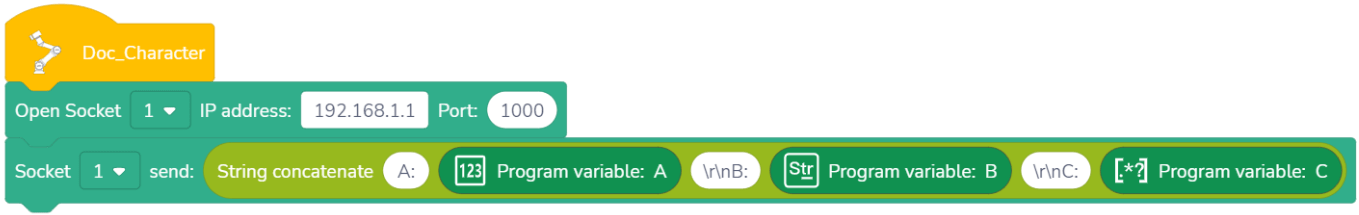
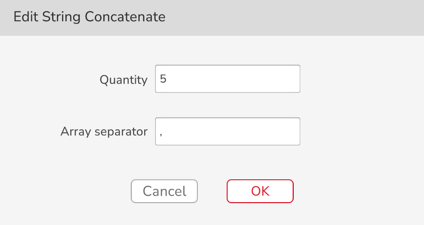
String Concatenate

Meaning: Concatenate the dragged variables or input strings in a certain order.
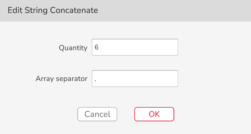
Application: Click this command to edit the number (number of the white oval box: 1~8) and the array separators. Drag in variables or input strings. This command can return the concatenated string, and the returned value is a string variable.
Example: Connect the following variables, A=8888, B=Hello, and C=[1,2,3,4,5,6], and the returned result is:
A:8888
B:Hello
C:1,2,3,4,5,6
The example program is as follows:
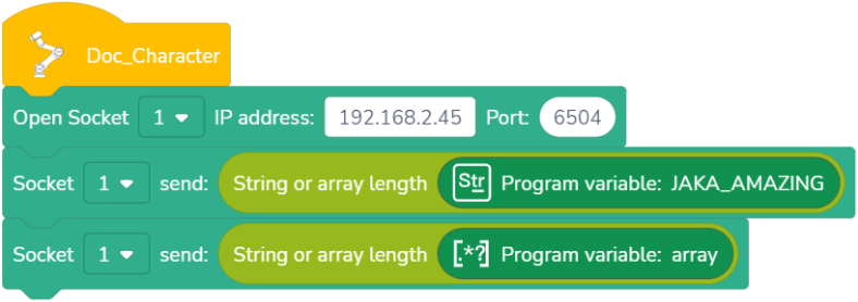
String or Array Length ()

Meaning: Calculate the length of a string or array and return the length value.
Application: Drag in a string variable or an array variable, or input a string, and the returned value is the length.
Example: If the host computer needs to obtain the length 12 of the string variable “JAKA_AMAZING” and the length 6 of the array variable [1,2,3,4,5,6], the example program is as follows:
String Compare

Meaning: Compare the size of two strings based on the ACSII code.
Application: Drag in string variables or input string values str1 and str2. If str1=str2, 0 is returned. If str1<str2, a negative value is returned. If str1>str2, a positive value is returned.
Example: For example, if you need to compare the size of string variables str1 and str2, the returned value should be negative. The example program is as follows:

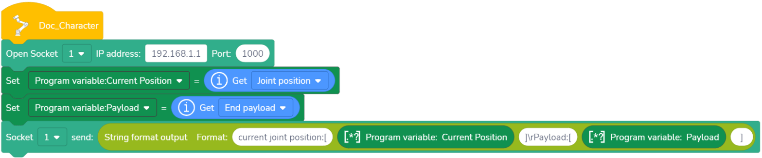
String Format Output

Meaning: The specified data is output as a string in the specified format.
Application: Click this command to edit the number (number of the white oval box: 1~8) and the array separators. You can drag in variables or input values. This command can return the formatted string, and the returned value is a string variable.
Example: Obtain the information about the robot:
Current joint position: [0,90,0,90,180,0]
End load: [0,0,0,0]
The example program is as follows:
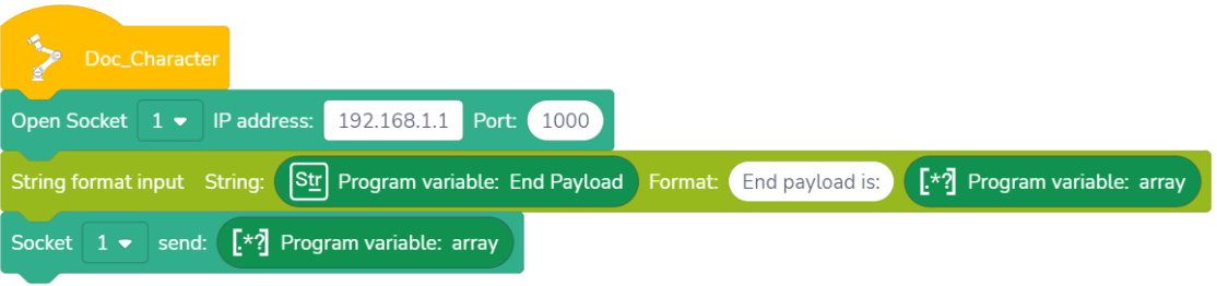
String Format Input

Meaning: Match a certain format of string and enter the matched data into the specified variable.
Application: Click this command to edit the number (number of the white oval box: 1~8) and the array separators. You can drag in the specified variable or input the value, and the required value can be extracted from the specified variable. Formatted result variables support integer, floating and string variables, or constants.
Example: Extract the array [0,0,0] in the string variable “End load is: 0,0,0”. The example program is as follows:

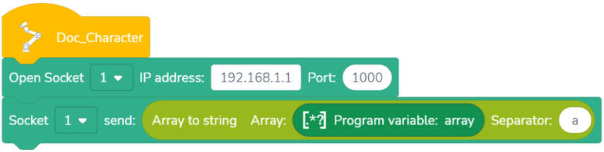
Array to String

Meaning: Converts an array into a string variable of a certain format.
Application: Drag in variables of the array type to be converted following the “array” and enter a string separator behind the separators.
Example: For example, to convert an array variable [1,2,3,4,5,6] to “1a2a3a4a5a6”, the example program is as follows:
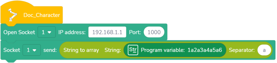
String to Array

Meaning: Convert a string of a certain format into an array variable.
Application: Drag in string variables to be converted into arrays following the “string” and enter a string separator behind the separators.
Example: For example, to convert the string variable “1a2a3a4a5a6” to an array variable [1,2,3,4,5,6], the example is as follows:
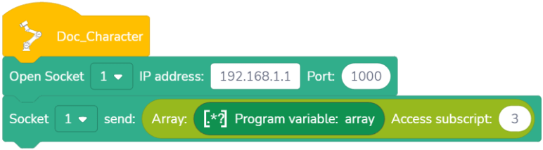
Access Subscript
You can access a variable in an array by setting an access subscript, or access multiple variables in an array at the same time by setting step.

Meaning: Access the elements in the array variable.
Application: Drag in the array variable to be accessed and enter the subscript value of the array to be accessed. The index of the subscript starts from 0, and the like. The command returns the element accessed.
Example: Access the value with the subscript 3 in the array variable [1,2,3,4,5,6], and the return value is 4. The example program is as follows:

Meaning: Access the elements in the array variable according to the subscript and step.
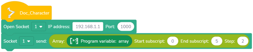
Application: You can drag in the array variable to be accessed and enter the subscript value and step of the array to be accessed. The index of the subscript starts from 0, and the like. The command returns the sub-array accessed.
Example: Access the value with the subscript 0,2,4 in the array variable [1,2,3,4,5,6], and the return value is [1,3,5]. The example program is as follows:
Set Array Elements

Meaning: Set the value of an element in an array.
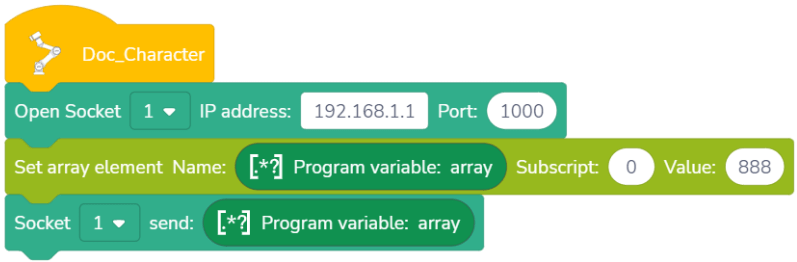
Application: Drag in the array variable to be set and enter the subscript value of the array element to be set. The index of the subscript starts from 0, and the like.
Example: For example, to set the value with the subscript 0 in the array variable [1,2,3,4,5,6] to 888, i.e. change the array variable into [888,2,3,4,5,6], the example program is as follows:
Communication Command
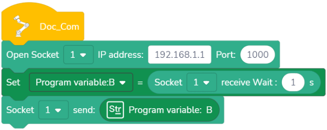
Open SOCKET

Meaning: Create TCP client and establish communication with TCP server.
Application: Select the specified SOCKET ID in the drop-down list, and enter the IP address and port number of the TCP server. When this command is run, a connection between the TCP client (robot) and the TCP server will be established.
Open SOCKET and Return Result

Meaning: Create TCP client, establish communication with TCP server, and return a socket value.
Application: Select the specified SOCKET ID in the drop-down list, and enter the IP address and port number of the TCP server. The TCP client (robot) and the TCP server will be connected when this command is run, and this command will get a returned value. If the connection is successful, it will return an integer value greater than 0; If the connection fails, the returned value is –1.
Close SOCKET

Meaning: Disconnect the specified SOCKET communication.
Application: Select the specified SOCKET ID in the drop-down list. When this command is run, the specified SOCKET communication connection will be disconnected.
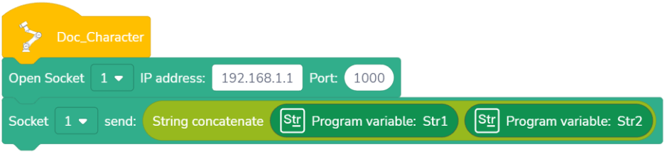
SOCKET Sending

Meaning: Make the controller send variables to the TCP server via SOCKET communication.
Application: Select the specified SOCKET ID in the drop-down list, drag in a variable or enter a value, run this command, and the TCP server will receive the content of this variable.
Note: The supported variable types include numbers, strings, and arrays. There is no special requirement for the format of the sent data, but Unicode characters are not supported.
SOCKET Send and Return Result

Meaning: Make the controller send variables to the TCP Server via SOCKET communication.
Application: Select the specified SOCKET ID in the drop-down list, drag in a variable or enter a value, run this command, and the TCP server will receive the content of this variable. This command will get a returned value. If the delivery is successful, the data length sent will be returned; If the delivery fails, the returned value is –1.
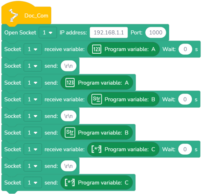
Example: Connect the SOCKET server, receive variables A, B, and C, and return the result. The example program is as follows:
SOCKET Receive Variable

Meaning: Wait for ( ) s until the variable is received. The controller will send a data request string, and then enter the receipt waiting state.
Application: Select the specified SOCKET ID in the drop-down list, and drag in the variable type to be received. If the variable is received within ( )s or not received even after the waiting time, the program will continue to run subsequent steps (if the waiting time is set to 0s, the robot will wait until the condition is met). Variable names containing Unicode characters are not supported.
Note: Variable types that can be received include numbers, strings and arrays, and the sending data format is:
Numbers: <variable name><data content>
Strings: <variable name><“data content”>
Arrays: <variable name><[data content]>
SOCKET Receive Array

Meaning: The robot stops running within ( )s until it receives an array variable with a length of ( ). The controller will send a data request string, and then enter the waiting state.
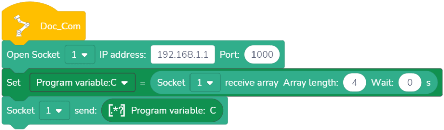
Application: Select the specified SOCKET ID in the drop-down list. If an array of less than or equal to the setup length is received within the setup time, the received array is returned. The missing element defaults to FLOAT_MAX, FLOAT_MAX = 340282346638528859811704183484516925440; If the received array is greater than the setup length, the App pops up an error and stops the program; If the array is not received, returns the empty array, the App does not pop up an error, and the program continues to run; If the time is set to 0, which means waiting until the condition is satisfied. The maximum waiting time is 65536 seconds. If it exceeds this time, treat it as a timeout.
Note: The sending data format is [n1, n2, n3…]
Example: Connect to the SOCKET server, receive the array variable C and return the result. The array length is 4.
SOCKET Receive Data

Meaning: The robot stops running within ( )s until the data is received. Unlike other receipt commands, the controller does not send additional data when running this command.
Application: Select the specified SOCKET ID in the drop-down list. If the data is received within ( )s or not received even after the waiting time, the program will continue to run subsequent steps (if the waiting time is set to 0s, the robot will wait until the condition is met). If the receipt is successful, return the strings received. If the receipt fails or exceeds the time, an empty string is returned.
Note: The variable type to be received is strings, and there is no special requirement for the sending format of server data. Unicode characters are not supported.
Example: Connect the SOCKET server, receive program variable B, and return the result.
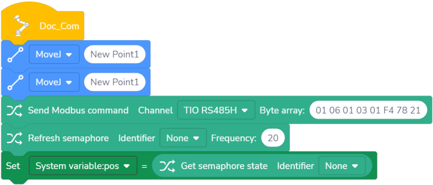
Refresh Semaphore

Meaning: Refresh the semaphore defined in【Settings】>【Hardware & Communication】>【Terminal I/O】.
Application: Select the semaphore to be refreshed in the command drop-down list, enter the refreshing frequency (Hz).
Refreshing frequency: Subject the bus broadband, the sum of the refreshing frequency of all signals does not exceed 125Hz, and the system will automatically regulate it.
Get Semaphore State

Meaning: Obtain the value of the semaphore.
Application: Select the required semaphore in the command drop-down list, and the value returned by the command is the value of semaphore.
Send Modbus Command

Meaning: Sending im/media/ente control commands for TIO external devices.
Application: Select the TIO channel used in the command drop-down list. You can enter a hexadecimal data command at the byte array, and do not need to add a verification code, for the system will automatically add it.
Example: Set the position of a device to 500 and obtain the position. The example program is as follows:
Subprogram Command
Subprogram

Graphical command subprogram
- Meaning: Some commands are formed into a independent program. If this program is added in the main program, the program will run the commands in this program. When the commands in this program are completed, return to its original position of the main program to continue running. This independent program is a subprogram.
- Application: Add a subprogram of the command editing type, edit an independent program segment in the subprogram and save it. This subprogram can be added at any time in the main program and can be reused.
Script command subprogram
- Meaning: The subprogram content is the preparation of a script syntax with a prescribed format.
- Application: Add a subprogram of the script type, edit the script syntax with the required format in the subprogram and save it. This subprogram can be added at any time in the main program and can be reused. Details of script programming refer to JAKA Script Programming Manual.
Operations
| Button | Name | Description |
|---|---|---|
 | Add subroutine | Click the add button on the right side of the subroutine title, select the type of subroutine, and click “OK”. After the creation is completed, the programming area will automatically go to the subroutine. |
 | Delete subroutine | Click the delete button on the right side of the subroutine title, click the trash can icon on the right side of the subroutine, and click “OK”. |
 | Exit subroutine | Click the exit button to exit the subroutine editing interface and return to the main program interface. |
Edit Subprogram
In the subprogram command bar or in the program, click the subprogram command to enter the subprogram editing interface. After editing the subprogram, save the main program again to ensure that the subprogram has been properly modified in the main program.
Variable Command
| Button | Name | Description |
|---|---|---|
| Add variable | Click the add button on the right side of the variable command bar, select the variable type, click “OK” to enter the variable setting interface, fill in the parameters, and click “OK”. Four types variables are available: system variables, program variables, speed variables, and position variables. |
| Delete variable | Click the delete button on the right side of the variable command bar, click the trash can icon on the right side of the variable to delete, and click “OK”. |
 | Filter variable | Click the check box to display or hide different types of variables. Show all types of variables by default. |
 | Edit variable | In the variable command bar or in the program, click the variable command to enter the variable editing interface. After editing the variable, save the main program again to ensure that the variable has been properly modified in the main program. |
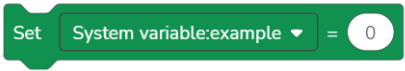
System Variable
There are two ways to create system variables. Besides adding it in this interface, you can also create and use it in【Settings】>【Program Settings】>【System Variables】. The system variable are variables in the control cabinet. When the robot is powered off or the program is deleted, this variable will not be cleared or disappear, and can be called in any program. The system variable type is number.
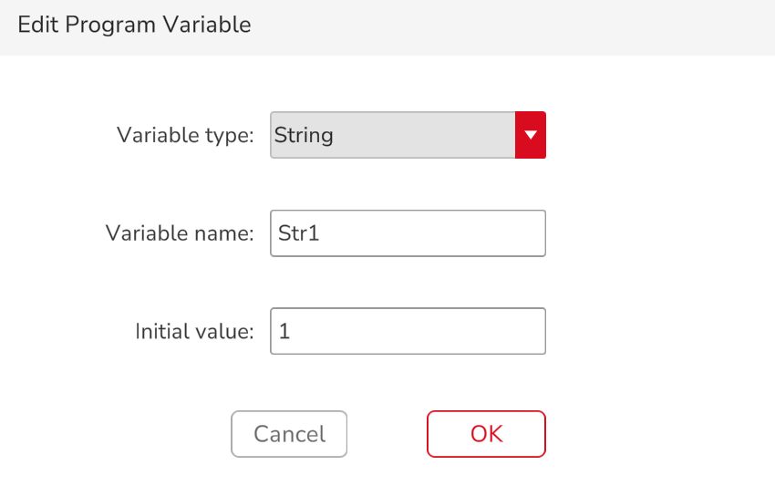
Program Variable

Program variables are variables created and used in the current program. The program variable can only be used in the program creating it. They are not available in other programs. If the program is deleted, the program variables created in this program will also be deleted. There are three types of program variables: number, string, and array.
Program variable naming supports Chinese format. Note that in the communication with third parties, variable names in Chinese may be displayed in garbled characters due to coding problems.
Speed Variable

The speed variable is a special variable that can be called on or off in the program by the global speed command in the movement command. The robot movement speed in the program can be controlled according to the actual working conditions. When the speed variable is called, the movement speed after this command is subject to the speed selected in the speed variable, and the speed in the movement command does not take effect. Like program variables, the speed variable can only be used in the current program and cannot be used in other programs.
Note: The speed variable can be sent through the SOCKET command. The sending content includes the joint speed, joint acceleration, linear speed, and linear acceleration.
Position Variable

The position variable is a specific variable that applies to the movement command or position calculation command and cannot be called in other commands. The position variable can set the Cartesian position and joint position of the robot. You can click the text box to directly input, or click “Edit” to enter the robot manual operation interface to control the robot. When setting the Cartesian position, pay attention to the selection of the coordinate system. When the set coordinate system is inconsistent with the actual situation, there will be deviation of the robot position, which will cause potential safety hazards. When the position variable is inserted into the move command, the robot moves according to the point information in the variable of move command. Like program variables, the position variable can only be used in the current program and cannot be used in other programs.
In the white oval input box, enter values, variables, and values obtained by SOCKET to assign data to variables.
Note: If you want to assign values to the whole array variable, you need to add [] before and after the array.

If you assign a value to a string, you need to add “” (double quotation in English) before and after the string.

Extension Command
The extension command needs to be used with JAKA’s force control products.
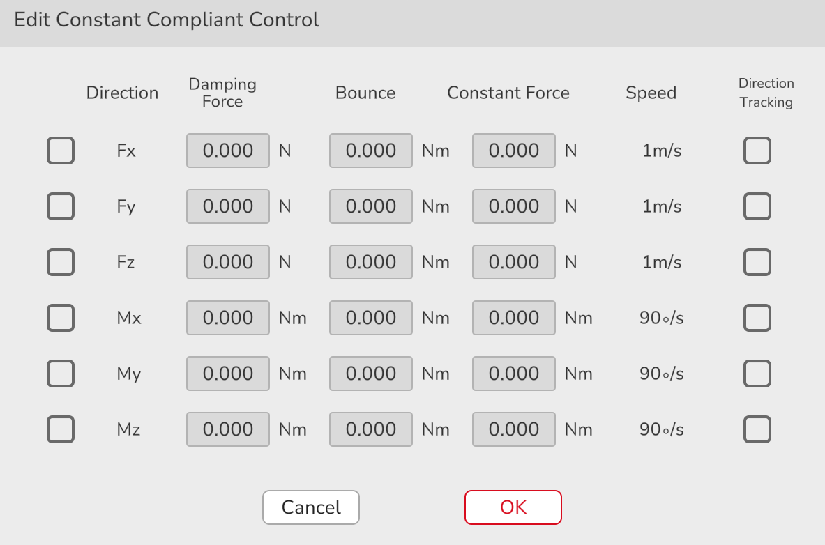
Constant Force Compliant Control
Constant force compliant parameter

Meaning: Set the compliant parameters in the constant force mode.
Application: Select the direction in which the force control function needs to be activated, and set the damping force, bounce force, and constant force, and select whether to activate direction tracking.
Damping force: The greater the rigidity of the external environment, the greater the damping force to be set; in the Freedrive mode, it is recommended to set the Fx, Fy, Fz greater than 10 N (2.25 lbf), Mx, My, Mz greater than 0.2 Nm (0.148 lbf·ft), and the setup value cannot be 0.
Bounce: Let the robot return to the preset trajectory; the larger the value, the less likely the robot will deviate from the preset trajectory.
Constant force: Ensure that the contact force between the end of the robot and the external environment is within the range of the set constant force value.
Open constant force compliant control

Open the constant force mode and select whether to initialize.
Initialize: compensate for the offset and payload of the force sensor (ensure that no external force is applied to the sensor in this mode).
Not initialize: adopt the previous compensation value.
Close constant force compliant control

Exit the constant force mode.
Speed Compliant Control
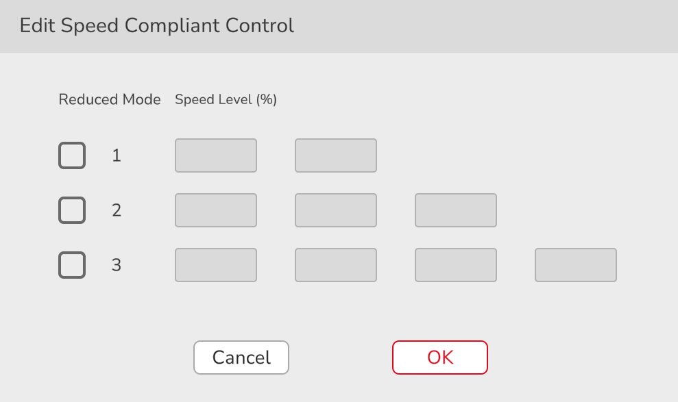
Speed compliant parameter

Meaning: Set the compliant parameter in the speed mode.
Application: Configure the deceleration level, and at most three-speed deceleration can be configured. When the force at the end of the robot is greater than the setup value of the force, the robot will decelerate until the sensor detection value is less than the set value of the control force. You can set the percentage of each deceleration to the original speed.
Open speed compliant control

Activate the speed mode and select whether to initialize.
Initialize: compensate for the offset and payload of the force sensor (ensure that no external force is applied to the sensor in this mode).
Not initialize: adopt the previous compensation value.
Close speed compliant control

Exit the speed mode.
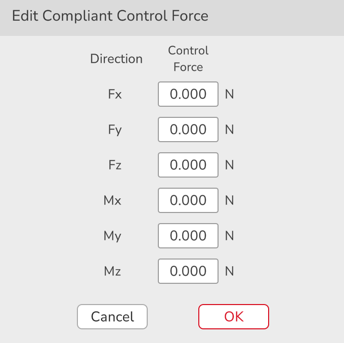
Compliant control force

This is used to set the force in the speed compliant control mode.
Motion Stop Condition

Meaning: Set conditions for early termination of movement.
Application: Select the direction to be monitored and set the upper or lower limit value. When the external force value is less than the lower limit value or greater than the upper limit value, this command is triggered. This command monitors the next move command. If the command is triggered, the robot will im/media/entely move from the current position to the position of the next move command.

Set Sensor Coordinate System

Meaning: Set the coordinate system used in the force control mode (to ensure that the direction of the coordinate system is consistent with the direction of the force sensor).
Application: If the TCP is selected, and the robot end position is based on the TCP; If the world coordinate system is selected, and the robot end position is based on the robot base coordinate system.